Disconnect your negative battery post and lay it aside.
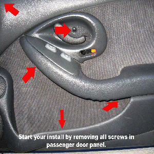
Remove all five visible screws from driver door panel with a Phillips head screwdriver.
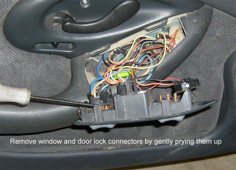
Gently pry up your driver window switch bezel, separating it from the door panel. Pry the connector off the switch and bezel; remove the handle bezel and the last door panel screw.
Once all 6 door panel screws are removed lightly pull up on the whole door panel assembly to separate the panel from the door. The panel is held on by plastic hook tabs. * Do NOT pry door panel away from door, it slides off in an upwards motion*
Next remove speaker screws. Remove and unplug speaker assembly.
Carefully pull back plastic water guard. You do not have to completely remove.
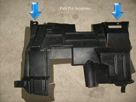
Remove driver and passenger side kick panel screws (4) on passenger side (5) on driver side and kick panel assembly. *pull kick panel toward rear of car to dislodge*
Remove lower driver (2 plastic push in tabs) and passenger (2 plastic push in tabs and one metal retainer) console cover.
Pop hood and remove PCM mounting bracket screws (2), pull PCM up and lay it aside.
Remove the firewall grommet that is now exposed. Pull it out and poke a hole into the grommet large enough for the red wire to feed though, and then re-secure grommet to firewall.
Take your red wire supplied with the kit and feed it though the hole you just made in the firewall grommet. * feed it from the hood/outside area to the cab/inside car area.
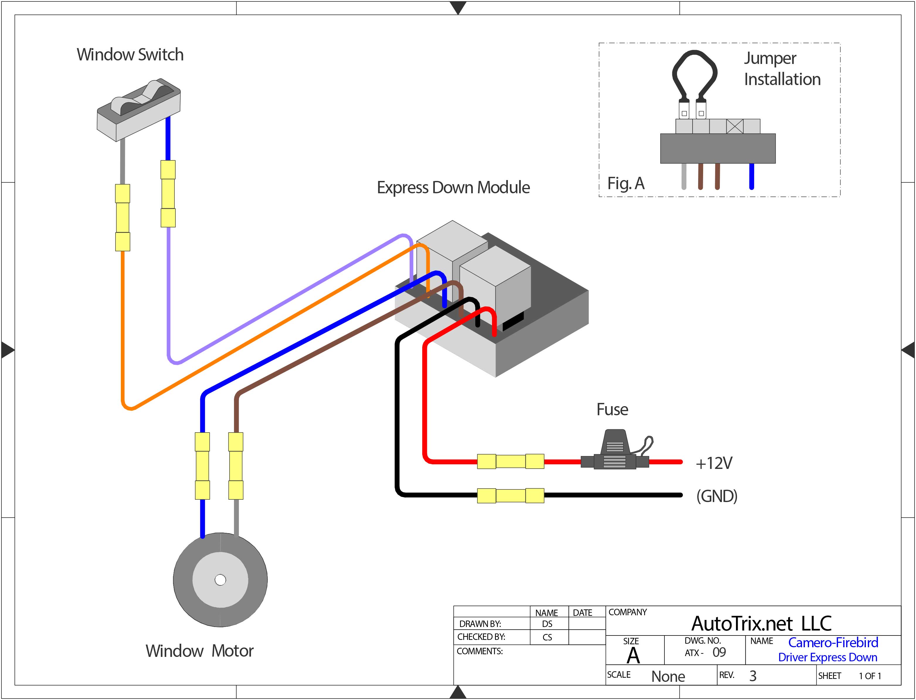
Pull wire lead into cab and across to driver side behind dash. You will find a pass through behind where the kick panel was. Route the orange,violet,blue, and brown wires through this hole into the rubber tube in between the cab and the door. We were able to use a 14mm wrench to aid with feeding wires though the pass thru into the driver door. The pictures below show only 2 wires, this is just a reference to show you how to route the 4 wires you will be running into the door.
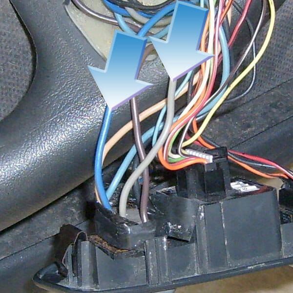
Cut two wires, (both of which are on the connector for the driver window switch) grey and dark blue of the window switch connector. Cut each at least 4 inches down from connector. Your window switch connector has six cavities.
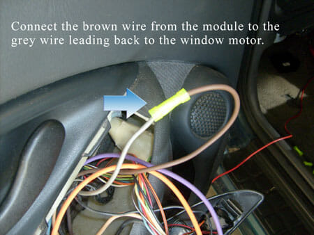
Crimp / Solder the brown wire from the express down module to the grey going to the motor.
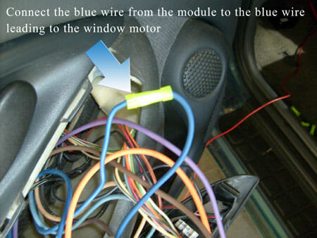
Crimp / Solder the blue wire from the express down module to the blue wire going to the motor.
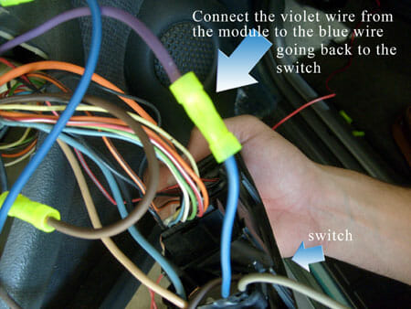
Crimp / Solder the violet wire from the express down module to the blue wire attached to the switch.
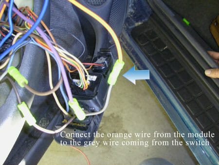
Crimp / Solder the orange wire from the express down module to the grey wire attached to the switch.
Crimp / Solder the red wire from the express down module to the red wire ran from the battery.
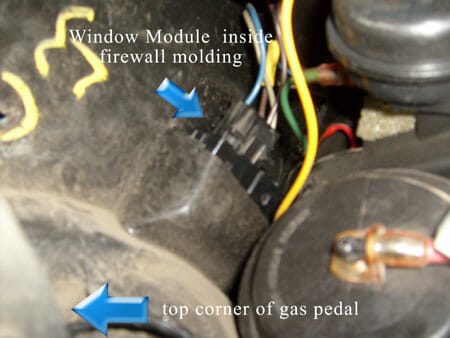
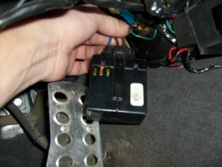
Locate and remove your factory express down module. Just under the dash above the transmission bell housing hump on the driver side.
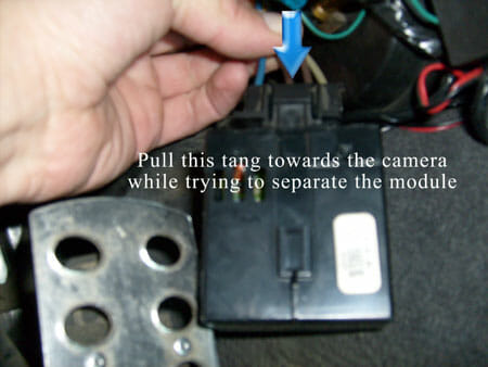
Remove module from plug. Insert supplied wire jumper into the grey and brown wires closest to each other. Refer to Fig A on above schematic. You will NOT utilize the factory module any longer. It can be disposed of and the provided jumper will stay plugged into factory plug as shown in Fig A on above schematic.
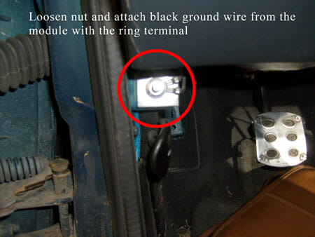
Attach the black ground wire from the express down module to the factory ground stud.
93-97 Attach your eyelet terminal to the power stud on your driver wheel well. Attach inline fuse holder to end of positive wire. Fuse holder must be within 6 inches of power source.
98-02 Route your Red wire across radiator support (in factory loom) to Positive Stud on the driver’s side wheel well. Attach inline fuse holder to end of positive wire. Fuse holder must be within 6 inches of power source.
Temporarily plug in your window switch, hook up your negative battery lead, turn on your ignition and test the operation of your driver window.
Re-install PCM, kick panels, door panel, and lower console covers.
If you are having any trouble with your installation, please feel free to Contact Us. You may also find posts from people who have installed our kits on www.ls1.com helpful, along with community input on your issue.